


Aluminum machining can be efficient, but it depends on how you set up the process. CNC aluminum parts are used across a wide variety of industries, and aluminum has many alloy grades, each with different properties. Different aluminum alloys and tempers can behave differently during machining, so the same approach is not appropriate for every job. Tool geometry, cutting speed, feed, chip evacuation, and setup planning all affect CNC machining efficiency.
In this blog, we’ll cover five practical tips for machining aluminum, from choosing the right alloy and tool to setting cutting parameters, managing chips and heat, and reducing unnecessary setups.
Know the Aluminum Alloy and Temper Before Machining
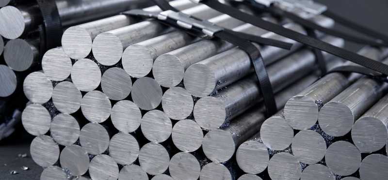
Before aluminum machining, the first step is to understand aluminum grade behavior. Aluminum 6061, 7075, and 2024 are all aluminum alloys but have different strength, hardness, and machining characteristics, so the same machining parameters may not work for every alloy.
Common Aluminum Alloys and Their Behavior
Aluminum 6061-T6 is a common grade for many CNC machining parts becuse its offers good machinability along with strength, corrosion resistance, and good workability. The temper also matters; for example, 6061-T8 and 6061-T9 have better chipping characteristics than 6061-T6.
Here are a few commonly used grades and their behavior.
| Aluminum alloy | CNC machining behavior | What to keep in mind |
|---|---|---|
| 6061 | Good to excellent machinability. It offers a useful balance of strength, corrosion resistance, and workability. | A practical choice for general CNC machined parts. The temper can change machining behavior. |
| 7075 | Machines well, but its higher strength and hardness can require different cutting conditions compared with 6061. | Choose it when the part needs higher strength. Do not use the same cutting data as 6061 without checking the tool manufacturer's recommendations. |
| 2024 | Has good machining characteristics along with high strength and good fatigue performance. | Its lower atmospheric corrosion resistance compared with many aluminum 6000-series alloys can matter when the finished part sees the environment directly. |
Why Alloy Choice Matters for Efficiency
The alloy and temper you machine can affect the cutting conditions and chip control. A process that works well for 6061 may need different parameters when you switch to 7075. Check the material condition before setting your machining parameters, then use the tool manufacturer's recommended starting data for that material.
Knowing the alloy before machining helps you adjust the machining approach instead of treating every aluminum job the same.
Shop-Floor Tip
Keep a small bar of common aluminum alloy grade if possible, and use a test cut when you need to verify machining conditions before production.
Use Tool Geometry Designed for Aluminum
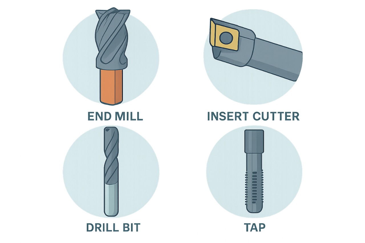
In CNC machining, a cutting tool is required that can remove material cleanly and evacuate chips from the cutting area. Tool geometry affects cutting force, chip evacuation, built-up edge, and surface finish.
Key Factors for Aluminum Tooling
Aluminum end mills are available with positive cutting geometry and higher helix angles. A positive rake helps reduce cutting forces, while a higher helix can support chip evacuation and efficient cutting in suitable operations. Aluminum end mills are available with 35°, 40°, and 45° helix options for aluminum, with the right choice still depending on the operation.
Polished flutes and rake surfaces are also used in aluminum-specific tooling. Some carbide end mills have polished flutes, while some aluminum inserts have polished rake surfaces that can help with chip flow and built-up-edge control.
Flute count also matters because aluminum can produce a large volume of chips. Two- and three-flute end mills are common choices, while higher flute counts leave less chip space. The right flute count still depends on the operation, machine setup, and material-removal target.
End Mills and Inserts
Some solid carbide end mills are available in aluminum-specific designs with sharp cutting edges, polished flutes, and high-helix geometry. Two- and three-flute tools can work well for many aluminum milling operations.
For larger milling operations, aluminum-specific indexable cutters can use positive-rake and polished inserts. These tools can support higher material removal rates when the machine, workholding, and cutting conditions can handle the load. PCD tooling also exists for aluminum machining.
Shop-Floor Tip
Before using a cutter, check the cutting edge for visible chipping, wear, and aluminum buildup. A damaged edge can affect surface finish and cutting performance.
Control Speeds, Feeds, and Depth of Cut
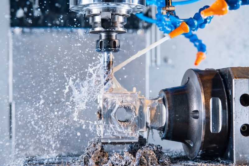
In aluminum CNC machining, speeds, feeds, and depth of cut need to work together. The right values depend on the aluminum alloy, tool diameter, flute count, tool geometry, machine capability, and machining operation.
Cutting speed controls how fast the cutting edge moves through the material. Spindle speed depends on the cutting speed and tool diameter. Feed per tooth tells you the feed distance per tooth during one revolution, while feed rate is the actual movement of the tool through the material.
Depth of cut also matters. A deeper cut can remove more material in one pass, but material removal also depends on radial engagement and feed rate. Tool rigidity, material, cutting-edge geometry, and the machining method all affect the suitable depth of cut.
Carbide End Mill Starting Points for Aluminum 6061 and 7075
The table below gives starting points for a specific 3-flute carbide exchangeable-head end mill machining A6061 and A7075 in a shoulder-milling operation at L/D = 3. These values come from a specific tool data set, so use them as a starting point and check the tool manufacturer's data for the actual end mill and machine.
| Tool diameter | Cutting speed | Spindle speed | Feed per tooth | Feed rate | Axial DOC | Radial width |
|---|---|---|---|---|---|---|
| 10 mm | 500 m/min | 16,000 rpm | 0.117 mm/tooth | 5,600 mm/min | 8 mm | 3 mm |
| 12 mm | 500 m/min | 13,000 rpm | 0.118 mm/tooth | 4,600 mm/min | 9.6 mm | 3.6 mm |
| 16 mm | 500 m/min | 9,900 rpm | 0.153 mm/tooth | 4,500 mm/min | 12.8 mm | 4.8 mm |
| 20 mm | 500 m/min | 8,000 rpm | 0.175 mm/tooth | 4,200 mm/min | 16 mm | 6 mm |
| 25 mm | 500 m/min | 6,400 rpm | 0.211 mm/tooth | 4,100 mm/min | 20 mm | 7.5 mm |
These values are not fixed settings for every 6061 machining job. Different end-mill designs and machining operations can use different cutting data. Start with the tool manufacturer's recommended values, then adjust them for the actual machine, workholding, tool reach, and cutting condition.
Shop-Floor Tip
Listen closely to the cut. A steady cutting sound usually means the tool is cutting normally. Squealing can point to rubbing, while a hammering sound can indicate vibration. Check the depth of cut, tool setup, workholding, and cutting conditions when the cut becomes unstable.
Manage Heat and Chip Evacuation
Aluminum machining produces heat and a large amount of chips, and heat can leave through the chips, coolant, tool, and workpiece. Good chip evacuation helps prevent recutting, tool wear, poor surface finish, and interruptions during machining.
Coolant Strategies
Coolant can help control temperature, provide lubrication, and move chips away from the cutting area. But every aluminum machining operation does not need the same coolant method. Some roughing operations can run without coolant when the chips carry enough heat away and chip evacuation remains under control.
When you use coolant, direct it toward the cutting zone so it can reach the area where chips form. Internal coolant can help when external coolant cannot reach the cutting area effectively, especially in deeper features. Do not assume higher coolant pressure always gives better results. Pressure and flow serve different purposes in chip control and chip evacuation.
Chip Control
Keep chips out of the cutting area as the tool moves through the aluminum. Long chips can wrap around the tool, while poor chip evacuation can cause chips to remain in the flutes and get cut again. This chip recutting can increase tool wear and may damage the workpiece.
Pay extra attention to pockets and other areas where chips have limited space to escape. Use the available coolant, air blast, tool geometry, and toolpath to move chips away from the cut. The goal is simple: keep the cutting edge working on fresh material instead of cutting the same chips again.
Shop-Floor Tip
Check the tool shank for contact marks after a deep cut. If the shank is rubbing the part, increase clearance or use a reduced-neck tool. Keep the tool as short as the job allows to maintain rigidity.
Plan the Process for Fewer Setups
Reducing unnecessary setups can save setup time and reduce repeated part alignment. The goal is not to force every part into one setup. Plan the workholding so the part stays stable, the tools can reach the required areas, and you do not have to reposition the part without a good reason.
Fixture Strategies
Start with stable locating surfaces and use the fixture to position the part consistently. Locators position the workpiece, while clamps hold it against those locators during machining. Position the workholding so cutting forces act into the support and locating structure where practical, and avoid excessive clamping force that can deform the part.
Keep clamps and supports clear of the cutting path. Check tool access before machining so the fixture does not block the cutter from reaching important features. You can also include the fixture in the CAM setup to check clearance and avoid collisions.
For repeat production, use locating features that let the operator load the part in the same position each time. Modular and quick-change workholding can reduce changeover time when you need to change fixtures repeatedly.
Do not reduce the setup count at the expense of rigidity, tool access, and part location. Sometimes a second setup gives the machine better access and provides a more stable way to finish the part.
Shop-Floor Tip
Keep a laminated setup sheet by the machine. Include the clamping order, torque specifications, tool numbers, and offsets. This gives operators the setup information they need and helps keep repeated cycles consistent.
Troubleshooting Common Aluminum Machining Problems
When an aluminum machining job starts creating problems, first identify the symptom before changing the machining conditions. The same problem can have more than one cause, so check the tool, workholding, cutting conditions, and chip evacuation together.
The following table provides example starting data for aluminum machining and should not be treated as fixed settings for every job.
| Problem | Possible causes | What to check |
|---|---|---|
| Built-up edge | Low cutting speed, light chip load, poor lubrication, unsuitable tool geometry | Check cutting conditions, tool edge, coolant or lubrication, and aluminum buildup on the tool |
| Chip packing | Too many flutes for the operation, limited chip space, poor coolant flow, difficult chip evacuation | Check flute space, coolant direction, chip flow, and cutting depth |
| Chatter or vibration | Long tool overhang, weak workholding, excessive engagement, unsuitable cutting conditions | Check tool stickout, holder, fixture rigidity, radial engagement, and cutting parameters |
| Poor surface finish | Chatter, built-up edge, worn tool, runout, poor chip evacuation | Check the cutting edge, holder, runout, tool stability, and chip removal |
| Excessive tool wear | Excessive heat, unsuitable cutting speed, rubbing, poor chip evacuation, unsuitable tool geometry | Check speed, feed, tool geometry, coolant, and chip evacuation |
| Tool breakage | Excessive cutting load, chip packing, chatter, excessive tool overhang, poor workholding | Check cutting load, tool reach, fixture rigidity, chip evacuation, and cutting conditions |
| Burrs | Worn tool, unsuitable cutting conditions, poor edge support, part geometry | Check tool condition, cutting conditions, workholding, and the machined edge |
These problems can often be traced back to a combination of tool condition, cutting parameters, rigidity, and chip evacuation. Make one controlled change at a time when troubleshooting so you can identify what actually improves the process.
Conclusion
The right aluminum machining approach depends on the part, material, tooling, and production requirements. Before starting the job, confirm the alloy and temper, choose suitable tooling, set cutting data for the actual tool and operation, and make sure the setup gives you enough rigidity and chip clearance. This helps you decide where to push machining conditions and where a more controlled approach is needed.
We manufacture custom CNC aluminum parts to customer drawings and samples. Share your drawing, material grade, quantity, and machining requirements with us, and we’ll review and provide a quotation.