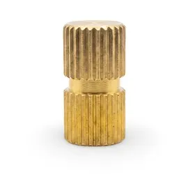

We manufacture custom brass threaded inserts for OEM plastic injection molded parts, produced strictly to customer drawings with defined thread standards, controlled OD, and specified knurl geometry. We cut them to perfect fit that hold, moves, flexes, and shrinks over time. Every batch we dispatch goes to through tight quality checks, quality thread gauge inspections, and real press-fit logic.
Our brass thread inserts are engineered for parts that hold, move, flex, and shrink over time. Every production batch undergoes strict QC inspection and Go/No-Go thread gauge checks to ensure consistent retention and torque performance.
Send Your Drawing for a Custom Brass Threaded Insert QuoteA brass threaded insert is a small metal fasteners placed inside a plastic part to create a strong internal thread. Note that brass inserts are primarily designed for plastics and soft composite materials, rather than solid hard metal blocks. For sheet metal fabrication applications, specialized steel press-fit/rivet nuts are typically used instead.
It replaces weak plastic threads that can strip when a screw is tightened. The insert is locked into the plastic by press-fit, heat-set, mold-in, and ultrasonic installation. This allows screws to be installed, removed, and reinstalled many times without damaging the plastic.
For a broader overview of brass inserts for plastic injection molding, see our main brass inserts page.
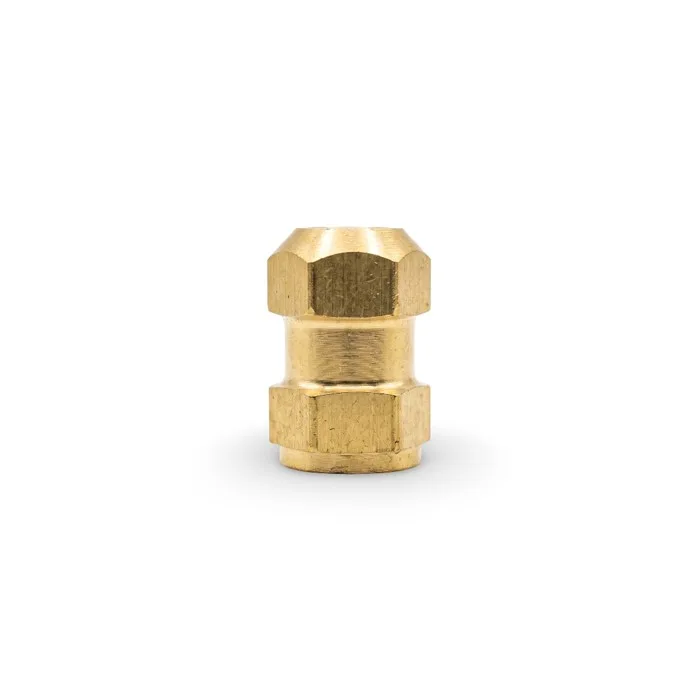
Material: Brass
Insert Type: Closed-End Hex Brass Threaded Bush Insert
Thread: M5 Internal Thread
Standard: DIN 16903-3
Hex Size (Across Flats): 7 mm
Overall Length: 10.8 mm
Outside Diameter: Ø7 mm
Body Diameter: Ø6.4 mm
Shoulder Length: 1.0 mm
Body Step Length: 2.5 mm
Corner Radius: R0.6 mm
Internal Thread: M5, Closed End
Custom M5 closed-end hex brass threaded bush insert manufactured with a 7 mm across-flats hex body, Ø7 mm outside diameter, and 10.8 mm overall length. The insert features an internal M5 closed-end thread, a stepped shoulder design, and is manufactured to DIN 16903-3 Used in automotive plastic components requiring durable threaded fastening.
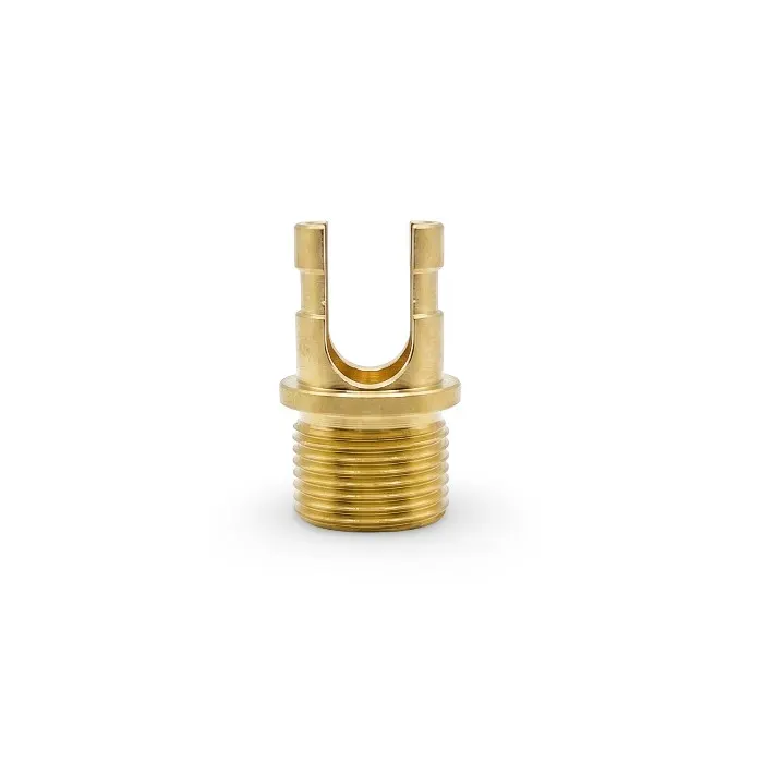
Material: Brass C36000 grade
Manufacturing Process: CNC Turning and Milling
Insert Type: Slotted Brass Threaded Insert
Thread: 15/32-32
Overall Length: 0.859"
Head Diameter: Ø0.532"
Thread Outside Diameter: Ø0.4687"
Slot Diameter: Ø0.320–0.3165 THRU
Key Slot Width: 0.075"
Upper Bore Diameter: Ø0.437"
Internal Relief Diameter: Ø0.406"
Thread Relief: 0.046 in Wide × Ø0.421"
Chamfer: 1/64 × 45°
Custom CNC machined slotted brass threaded insert manufactured with a 15/32-32 thread, 0.859 in overall length, and Ø0.4687 in threaded outside diameter. The insert features a through key slot, thread relief, and a 1/64 × 45° chamfer, manufactured according to the specified drawing dimensions.
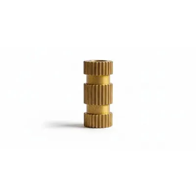
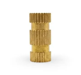
Insert Type: Long Straight Knurled Press-In Brass Threaded Insert
Thread: ISO Metric (M6)
Outer Diameter (OD): Ø8.90 mm
Reduced Center Diameter: Ø7.50 mm
Overall Length: 20.00 mm
Knurl Type: Straight Knurl
Upper Knurled Section Length: 4.00 mm
Center Knurled Section Length: 6.10 mm
Lower Knurled Section Length: 4.00 mm
Custom long straight knurled press-in brass threaded insert manufactured with an M6 ISO metric internal thread, Ø8.90 mm outside diameter, Ø7.50 mm reduced center diameter, and 20.00 mm overall length. The insert features three straight knurled sections to improve retention in plastic molded components and is designed for press-in installation in OEM plastic assemblies.
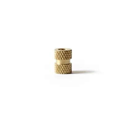
Insert Type: Diamond-Knurled Heat-Set Insert
Thread: ISO Metric (M6)
Outer Diameter (OD): Ø8 mm
Reduced Center Diameter: Ø6.50 mm
Overall Length: 10 mm
Knurl Type: Diamond Knurl
Knurled Section Length: 4 mm
Custom diamond-knurled brass threaded insert manufactured with an M6 ISO metric internal thread, Ø8 mm outside diameter, Ø6.50 mm reduced center diameter, and 10 mm overall length. The insert features diamond knurling on both ends with 4 mm knurled sections, heat-set installation in injection-molded and 3D-printed plastic components for electronics and industrial applications.
Material selection for brass threaded inserts depends on thread requirement, machining behavior, plating need, and final application. Free-cutting brass is used as the default material for insert production. Other brass grades are supplied according to customer drawing.
| Brass Grade | Composition | Key Properties | Typical Insert Use | Standards |
|---|---|---|---|---|
| C360 | Cu 60.5–63.5%, Pb 2.5–3.7%, balance Zn | Excellent machinability, stable thread quality | Standard threaded inserts for plastic and general industrial assemblies | ASTM B16, CDA 360 |
| C353 | Cu 60–63%, Pb 1.5–2.5%, balance Zn | High machinability for faster production | High-volume insert production when faster machining is required | ASTM B16, CDA 353 |
| C385 | Cu 56–59%, Pb 2.5–4.5%, balance Zn | Machinable, suitable when appearance matters | Produced when specified for decorative and visible insert applications | ASTM B16, CDA 385 |
| Tin-Plated Brass | C360 base + 5–15 µm Sn | Corrosion resistance, smoother installation | Outdoor use, humid environments, electrical assemblies | ASTM B545 over ASTM B16 |
| Nickel-Plated Brass | C360 base + 5–20 µm Ni | Wear resistance, bright finish | Visible hardware, repeated assembly use | ASTM B689 over ASTM B16 |
We manufacture multiple brass threaded insert designs based on plastic type, installation method, and retention requirement. Each design type is produced to drawing with controlled OD, thread fit, and knurl geometry
We manufacture all of these above listed. Some batches need OD tolerance maintained down to ±0.05 mm and some need to thread pitch to be looked within class 2B. If your part calls for something not off the shelf, we can do it.
We manufacture brass threaded inserts in both Metric and Imperial thread systems because customers use different screw standards.
Metric (ISO) threads are widely used in Europe, much of Asia, and many modern automotive and electronics designs. UNC/UNF threads are still widely used in many legacy industrial and appliance applications in the USA.
We machine both thread systems and follow the fit class written on the customer drawing so the insert works reliably in plastic parts.
| Thread family | Fit class | Typical use | Common sizes |
|---|---|---|---|
| Metric (ISO) | Typical 6H when not otherwise specified | Global OEM products, electronics, and automotive plastics | M2, M3, M4, M5, M6, M8 |
| UNC/UNF (Imperial) | Typical 2B when not otherwise specified | USA legacy assemblies, appliances, and industrial plastics | 2-56, 4-40, 6-32, 10-32, 1/4-20 |
Other fit classes can be machined when they are specified on the drawing. All production threads are checked with Go/No-Go gauges and cleaned before shipment.
In one M5 production batch, plating buildup reduced internal thread clearance. We checked all 2000 pieces with Go/No-Go plug and identified 180 that failed inspection. Those parts were cleaned, re-cut, and rechecked before shipment. This is why our threads fit correctly when they reach the customer’s assembly line.
Typical dimensions shown below are reference ranges used in production. Final dimensions depend on insert type, knurl design, installation method, and customer drawing.
| Thread Size | Typical Length Range (mm) | Typical Outside Diameter Range (mm) | Common Use |
|---|---|---|---|
| M1.6 x 0.35 | 2 to 4 | 2.5 to 3.0 | Miniature electronics, wearables |
| M2 x 0.4 | 3 to 5 | 3.0 to 3.5 | Small electronics, mobile devices |
| M2.5 x 0.45 | 3 to 6 | 3.8 to 4.2 | Electronics, small appliances |
| M3 x 0.5 | 4 to 8 | 4.5 to 5.0 | Consumer electronics, automotive |
| M4 x 0.7 | 6 to 12 | 6.0 to 6.5 | Automotive, appliances, furniture |
| M5 x 0.8 | 8 to 15 | 7.5 to 8.0 | Power tools, heavy appliances |
| M6 x 1.0 | 10 to 18 | 9.0 to 9.5 | Industrial equipment, machinery |
| M8 x 1.25 | 12 to 20 | 12.0 to 13.0 | Heavy industrial, HVAC equipment |
| M10 x 1.5 | 15 to 25 | 15.0 to 16.0 | Machinery, structural assemblies |
| M12 x 1.75 | 18 to 30 | 18.0 to 19.0 | Heavy machinery, large equipment |
| Thread Size | Typical Length Range | Typical Outside Diameter | Common Use |
|---|---|---|---|
| #2-56 | 3 to 4 mm | approx. 3.2 mm | Miniature electronics, instrumentation |
| #4-40 | 4 to 6 mm | approx. 4.0 mm | Electronics, small devices |
| #6-32 | 5 to 8 mm | approx. 4.8 mm | Consumer electronics, appliances |
| #8-32 | 6 to 10 mm | approx. 5.5 mm | Automotive, industrial equipment |
| #10-24 | 8 to 12 mm | approx. 6.4 mm | Machinery, equipment housings |
| 1/4"-20 | 10 to 15 mm | approx. 9.5 mm | Industrial assemblies, heavy equipment |
| 5/16"-18 | 12 to 18 mm | approx. 11.9 mm | Machinery, structural applications |
| 3/8"-16 | 15 to 25 mm | approx. 14.3 mm | Heavy industrial equipment |
In real production, five dimensions matter most on a brass threaded insert:outer diameter, overall length, thread depth, entry chamfer, and knurl height.
Customers normally define these on their drawing instead of using standard products. We control each dimension during machining and inspection so the insert installs clean and holds reliably.
| Feature | How we control it | Why it matters |
|---|---|---|
| Outer Diameter (OD) | Machined to a tight tolerance and checked with precision gauges on every batch | Prevents spin-out and avoids cracking thin bosses |
| Overall Length | Cut exactly to the customer drawing | Matches boss depth and prevents bottoming |
| Thread Depth | Controlled in machining and verified with Go/No-Go gauges | Prevents screw bottoming and cross-threading |
| Entry Chamfer | Machined lead-in on every batch | Helps screws start straight and protects threads |
| Knurl Height | Measured and adjusted during production | Too high can crack the boss; too low can cause spin-out |
We treat OD as the main fit dimension, thread depth as the main functional dimension, and knurl height as the main retention control. Every production batch is checked against these three before shipment
Knurl geometry is one of the primary factors affecting how a brass threaded insert grips plastic.
Knurl pattern and height are defined on the approved customer drawing.
If retention adjustments are required after pilot validation, changes are implemented only through formal drawing revision.
Correct knurl geometry allows clean seating, good retention, and protection of thin bosses.
Incorrect knurl design can lead to spin-out even if the thread is correct.
Lower insertion force and smoother press-in feel. Works well when OD tolerance and hole size are consistent. Retention can drop if knurl height is too shallow.
Higher resistance to rotation due to cross-pattern engagement. Provides better anti-rotation in vibration conditions. Requires proper chamfer and taper to avoid installation damage.
Plastics such as ABS and unfilled PA66 may require slightly deeper knurl for proper grip.
Harder plastics such as PC and glass-filled grades require shallower knurl to reduce cracking risk, provided boss wall thickness supports the load.
Heat-set inserts require controlled knurl geometry to allow proper plastic flow during melt installation.
Knurl height is measured during production.
Tooling is adjusted when pilot validation or customer feedback indicates retention issues.
Knurl pattern is selected according to plastic material, installation method, and required retention. Final geometry follows customer drawing and insert application.
| Knurl Pattern | Typical Insert Use | Common Installation Method | Technical Reason |
|---|---|---|---|
| Straight Knurl | General-purpose threaded inserts | Press-in, heat-set | Simple grip and easy machining for regular plastic parts |
| Diamond Knurl | High-retention inserts | Heat-set, ultrasonic | Multi-directional grip improves anti-rotation and pull resistance |
| Helical Knurl | Controlled insertion inserts | Heat-set | Improves controlled insertion and axial grip in thermoplastics |
| Opposed / Custom Knurl | Custom OEM insert designs | Heat-set or drawing-specific installation | Used when retention pattern is defined by customer drawing |
Brass threaded inserts can be installed using different methods depending on the plastic material, application, and retention requirements. The installation method influences insert geometry, tooling, and long-term performance.
| Insert Type | Install Method | Tools Needed | Strength Profile |
|---|---|---|---|
| Press-In Threaded Inserts | Manual/Press | Arbor press, jig | High pull-out resistance |
| Heat-Set Threaded Insert | Heated tip | Thermal driver | Medium to high, fast fit |
| Self-Tapping | Screw-driven | Driver gun | Quick install, moderate strength |
| Expansion | Threaded bolt expands body | No external press | High lock after set |
Threaded insert type is selected according to plastic material, installation method, and required retention. Different plastics respond differently to heat, pressure, and insert geometry, so final insert selection follows application needs and customer drawing.
| Plastic Material | Recommended Insert Type | Installation Method | Reason |
|---|---|---|---|
| ABS | Heat-Set / Ultrasonic | Controlled heat and ultrasonic insertion | Good retention with moderate wall strength |
| PC | Heat-Set / Ultrasonic | Heat-set and ultrasonic depending on insert geometry | Strong material with reliable thread holding |
| PA6 (Nylon) | Heat-Set / Mold-In | Heat-set and molding during part production | High retention and strong pull resistance |
| POM | Press-In / Controlled Heat-Set | Installation method selected after fit validation | Dimensional stability requires controlled insert fit |
| PP | Larger OD Heat-Set Insert | Heat-set with larger boss support | Lower retention, needs stronger surrounding wall |
| Thermoset Plastics | Press-In | Mechanical insertion | Heat methods are generally not suitable |
Heat-set insert performance changes with plastic type, boss thickness, boss temperature, and installation tooling. Because of this, there is no single hole size that works for every project. Publishing one fixed number does not reflect real production conditions.
Where possible, we adjust the insert itself so the customer’s mold does not need to change. If the boss design is fundamentally unsuitable, a mold change may still be required. For every new job we control and fine-tune key features:
Where required, vent features are added so softened plastic can flow around the insert instead of trapping pressure.
For first runs we supply pilot inserts made strictly to the approved drawing. The customer installs the samples on their production line. Installation performance depends on their plastic, boss design, and tooling
If the customer later requests a change for easier installation, we review the drawing and adjust features such as OD and knurl only after mutual agreement. Any revision is treated as a formal drawing update before new samples are produced.
Our responsibility is to make inserts accurately to the agreed drawing and maintain the same quality in every batch.
A brass expansion threaded insert is designed to spread outward when a screw is driven in. The body has slots that allow controlled expansion. This expansion presses against the plastic in addition to the knurl grip.
Maker use expansion inserts when normal press-in types do not hold well in a specific plastic design. They work best in softer plastics and thin bosses, provided the boss can tolerate outward pressure. They are useful when customers want mechanical locking without using heat tools.
The insert only locks after the screw is installed. Because of this, expansion inserts handle small hole-size variation better than rigid press-fit types.
We ream the insert bore clean so expansion happens smoothly and repeatably without burr interference.
| Insert type | Install method | Best plastics | Main risk | Typical retention (when design is correct) |
|---|---|---|---|---|
| Press-in | Mechanical press and arbor press | ABS, PC, general rigid plastics | Boss cracking in thin walls | High |
| Heat-set | Heated tip and thermal press | Nylon, PEEK, heat-tolerant plastics | Sink marks, insert float, and uneven temperature | Medium to high |
| Expansion | Screw-driven expansion | Softer plastics & variable holes | Over-expansion from high torque | High after screw is set |
Each method behaves differently. Press-in inserts need sharp, consistent knurl and tight OD control. Heat-set inserts need tapered bodies and clean chamfers for smooth melt flow. Expansion inserts rely on slot design and a smooth internal bore.
Choose the method that matches your plastic, boss design, production speed, and torque requirement.
We cut threads with carbide taps and single point tool. It is depending on thread depth and geometry. After cut:
Some of our flanged closed-end inserts require blind threads controlled to within ±0.10 mm from the base. This is achieved through setup checks, controlled tooling stops, and correctly matched thread relief bores.
We do not ship threads we would not bolt into ourselves.
Threaded inserts fail for predictable reasons. Many production-related failures are caused by tolerance drift, tool wear, and plating variation. We monitor these during production so problems are corrected before shipment.
Knurl height too shallow, OD too small, or plastic mismatch.
We measure OD during the run and verify knurl height. If retention feedback changes, we adjust knurl geometry before the next batch.
Tap wear, chip packing, and material smearing, especially in free-cutting grades such as C36000.
Scheduled tap replacement, air-blast cleaning after cut, and Go/No-Go gauge verification before packing.
Collet drift and OD wear during long production runs..
In-process OD checks with precision gauges. If tolerance shifts, the lot is corrected before dispatch.
Nickel and tin plating adds thickness inside the thread profile.
Controlled pre-plate sizing and gauge inspection after plating to ensure proper fit.
Each batch is verified for thread fit, OD tolerance, and repeatability before shipment.
We manufacture most brass threaded inserts on dedicated automatic insert machines. These machines are designed for high-volume production with stable outer diameter tolerance control, repeatable knurl forming, and integrated tapping stations within the automatic cycle. Standard insert production is not done on general-purpose CNC lathes.
CNC turning is used only for large inserts, special geometries, and when parts requiring tighter features.
Automatic insert machines perform OD turning, knurl forming, facing, and threading in a fixed production sequence. Because each setup is dedicated to one insert type, dimensional consistency remains stable across the batch.
Tool wear is monitored during production. If OD and knurl height begins to shift, tooling is adjusted immediately to maintain tolerance.
Internal threads are produced using integrated tapping stations within the automatic cycle. Tap condition affects pitch accuracy and surface finish, so taps are replaced based on production count, not after failure.
Every batch is verified using calibrated Go/No-Go plug gauges. For plated inserts, threads are checked again after plating to confirm coating thickness has not affected fit.
Specialty inserts are produced on CNC machines using single-point threading to maintain concentricity between thread and outer diameter.
Knurl patterns are formed using dedicated knurling tools to maintain consistent depth and pitch. Knurl height is monitored during production because it directly affects retention.
Shallow knurl reduces grip. Excessive knurl increases installation stress. Tool wear is tracked to prevent profile drift during long runs.
Outer diameter is checked with precision gauges during production. Thread fit is verified before packing. Plated parts receive post-plate inspection to confirm functional engagement.
Machine settings, tooling configuration, and production parameters are recorded for repeat orders. This supports consistent batch performance using the same validated setup.
Threaded inserts are packed according to thread sensitivity and surface finish.
Repeat orders typically ship within 15–20 working days.
New parts requiring tooling or plating may require 20–25 working days
Making one batch right is normal. Making the same part the same way months later is where process control matters. For repeat orders, we do not restart from zero.
We run the same validated setup used on previous production, whether the part runs on automatic insert machines or CNC for special features.
Machine settings, tooling stops, and production parameters are stored for repeat runs. This helps maintain the same dimensions across batches.
The same collets, clamps, and holding methods are used to keep OD, thread pitch, and knurl repeatable.
Go/No-Go gauges are selected according to the customer’s tolerance class when specified.
Sample part photos from inspection are archived to maintain visual and dimensional consistency.
We do not just repeat the drawing. We repeat the manufacturing process.
It depends on plastic type, boss size, hole diameter, boss wall thickness, and installation method. We review your drawing and usually supply pilot inserts for validation before mass production.
Spin-out is normally caused by incorrect hole size, shallow knurl height, and weak plastic material. Retention must be validated in real production, not assumed from catalog data.
Yes. We manufacture non-standard threads for OEM clients across our entire range of Brass Products. We need a clear thread pitch and tolerance zone in the drawing.
Yes. We regularly manufacture closed-end inserts. Short inserts with limited full thread engagement can be manufactured when the drawing supports it. Short-form taps and single-point threading are used to control thread start and finish.
Yes. We supply pilot samples before production tooling is finalized. Mass production begins only after validation.
Threads are checked again after plating. If coating buildup affects fit, threads are re-verified and adjusted before shipment.
Yes, we handle efficient shipping to the USA, UK, and throughout Europe. We are a leading supplier for Threaded Inserts in the Netherlands and provide high-quality Brass Threaded Inserts in Germany, as well as other international territories.
Yes. Material certificates and inspection reports are available when required. Thread fit is verified with gauges before packing.
To request a quotation for brass threaded inserts, please send your drawing along with RFQ details.
Please include:
Send your RFQ and drawings to receive a quotation with pricing and indicative lead time.