Sheet metal fabrication is a manufacturing process used to cut, bend, and join metal sheet into functional parts.
The process is commonly used to produce brackets, panels, enclosures, frames, and structural components. These parts are widely used in electrical equipment, automotive systems, HVAC assemblies, and industrial machinery.
We provide custom sheet metal fabrication service based on customer drawings and specifications. Parts are manufactured for prototype and production requirements.
Request Quote Today for Custom Sheet Metal Fabrication Parts
| Specification | Details |
|---|---|
| Materials Supported |
Mild steel (CRCA, HR) Galvanized steel Stainless steel 304, 316 Aluminum 5052, 6061, 6063 Brass (grade to be confirmed per requirement) Or as per customer requirements |
| Thickness Range | 0.30 mm to 6.00 mm |
| Maximum Blank / Part Size | To be defined based on cutting and bending capacity |
| Cutting Tolerance | ±0.1 to ±0.3 mm (depends on material and thickness) |
| Bending / Forming Tolerance | ±0.5° to ±1.0° (depends on material and bend length) |
| General Fabrication Tolerance | As per customer drawing or agreed standard |
| Standard Finishes Offered |
Powder coating (via partner) Zinc plating (via partner) Anodizing (via partner) Brushing Polishing |
| Drawings Accepted | STEP (3D), PDF, DXF, and DWG files |
| Production Type | Prototype, low volume, mass production |
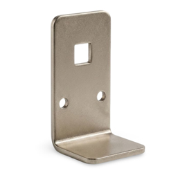
Custom steel sheet fabrication bracket produced from pre-galvanized G90 steel sheet, 11 gauge (3.05 mm) thick. Manufactured using press brake forming with a 90-degree bend, deburred edges, and as-received mill galvanizing with no secondary coating applied.
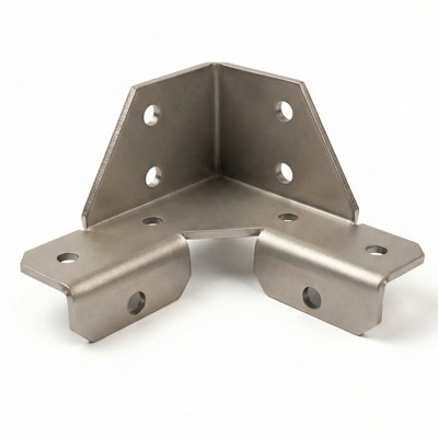
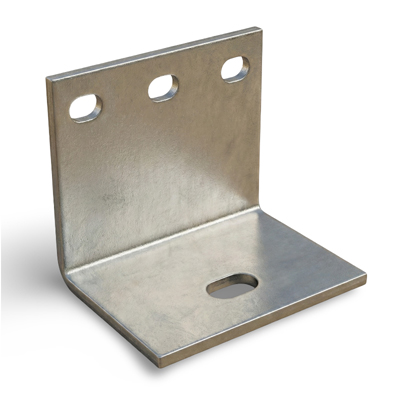
OEM press-formed sheet metal gusset manufactured from G90 galvanized steel, 12 GA thickness (0.105 in / 2.67 mm). Produced using dedicated forming dies with multiple 90° bends and controlled bend radii. Edges are deburred and the surface remains as-galvanized for corrosion resistance. Suitable for structural reinforcement and panel support applications in fabricated assemblies.
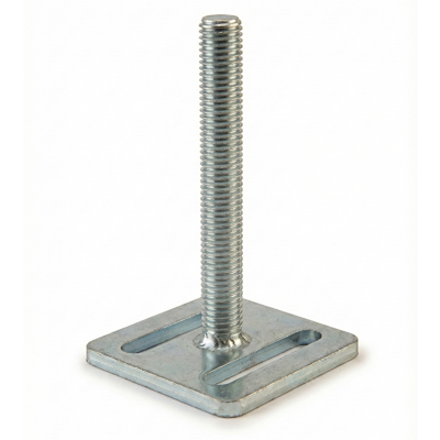
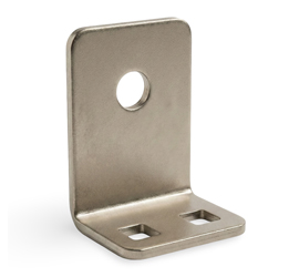
Sheet metal fabricated bolt-down foot assembly manufactured from laser-cut steel plate with elongated mounting slots. A standard M12 × 1.75 threaded stud is fillet welded to the base and zinc plated after fabrication for corrosion protection. Commonly used as an adjustable support or anchoring foot in industrial fixtures and equipment.
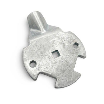
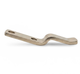
Zinc plated steel offset center cam manufactured by sheet metal forming. Designed for use with 8 mm square shaft handles in panel and enclosure locking mechanisms, providing controlled cam action for secure closure.
We perform laser cutting to produce flat sheet metal parts with required shapes and cutouts.
Punching operations are carried out using manual punching, mechanical press punching, and hydraulic press punching depending on the part requirement.
Custom metal stamping is used for repeat-production parts requiring consistent geometry. Stamping is performed using dedicated dies for blanking and piercing operations before secondary forming.
Bending is done using a combination of manual forming and CNC press brake bending. This allows us to produce simple bends as well as repeatable formed parts. Our metal cutting and bending services support both prototype and production sheet metal components.
Forming and hemming operations are supported for panels, covers, and enclosure components. These operations are used to improve strength and remove sharp edges.
We provide welding services using MIG, TIG, and spot welding. Welding is performed for aluminum, steel, and stainless steel parts and assemblies.
Threaded inserts and metal nuts are manufactured and installed as per customer drawings.
Secondary operations such as tapping and countersinking are also supported.
Surface finishing including powder coating, anodizing, and plating is provided through qualified partner facilities. All finishing work is done based on customer specification.
We support assembly and kitting of sheet metal parts. Full assemblies are provided depending on the project requirement.
We process stainless steel grades 304 for sheet metal fabrication. Common applications include enclosures, panels, and structural components. Typical thickness range is 0.3 mm to 3.0 mm. Stainless steel exhibits higher springback during bending, and bend angles are controlled through tooling selection and forming sequence adjustments.
Mild steel grades including CRCA and HR steel are widely used for general fabrication. These materials bend more predictably compared to stainless steel. Typical thickness range is 0.8 mm to 6.0 mm. Thin sections may distort during welding, and proper fixturing is required to control dimensional stability.
Aluminum alloys 6061 and 6063 are processed based on application requirements. 6063 is generally easier to form than 6061 and is preferred for complex bends. Typical thickness range is 1.0 mm to 4.0 mm. Bend radius selection is critical for 6061 to avoid cracking during forming.
Galvanized and pre-coated sheets are used for panels and enclosure components. Typical thickness range is 0.6 mm to 2.0 mm. Care is required during bending to prevent coating damage, and welding is supported with post-fabrication surface protection considerations.
Brass is mainly used for stamped parts and small electrical components such as terminals. It forms easily but is prone to surface marking during handling. Thickness is typically below 3.0 mm for stamping applications.
1. Thin sheet metal increases the risk of distortion during bending and welding.
2. Material behavior varies with alloy type and thickness.
3. Final tolerances depend on material selection, bend geometry, and welding sequence.
4. Drawings should clearly specify material grade and bend details.
Sheet metal fabrication tolerances depend on material type, thickness, and manufacturing sequence. Cutting, bending, and welding each introduce controlled variation.
The tolerance values below are general guidelines for small to medium sheet metal parts.
Laser cutting tolerance is typically within ±0.2 to ±0.3 mm under standard conditions. Achievable accuracy depends on material type and sheet thickness, with thinner sheets generally holding tighter tolerance.
Bending angle tolerance is typically within ±0.5° to ±1.0°. Angle variation is influenced by material springback, particularly in stainless steel and aluminum. Flange length after bending is typically controlled within ±0.5 to ±1.0 mm.
Hole position tolerance for flat laser-cut parts is typically ±0.2 to ±0.3 mm. After bending and welding, positional variation can increase to approximately ±0.5 mm due to deformation and heat input.
Flatness control depends on part size, thickness, and welding sequence. Thin sheet metal and large flat panels are more susceptible to distortion, especially after welding.
Dimensional inspection is performed using vernier calipers, height gauges, angle gauges, and Go/No-Go gauges. Final acceptance is based on customer drawings and application requirements.
Tight tolerances, large flat parts, and welded assemblies may increase manufacturing cost or lead time. Tolerance requirements are reviewed during the quotation stage to align manufacturability and expectations.
Sheet metal parts are easier to manufacture when basic design rules are followed. Parts are manufactured as per customer drawings. In some cases, we suggest design changes if a part is not possible to fabricate within normal sheet metal processes.
Bend radius should be selected based on material thickness and alloy. Very tight bend radii increase forming force and tool wear. Short flange lengths are difficult to bend accurately and may deform during forming.
Holes located too close to bend lines or part edges may distort during bending. Adequate clearance helps maintain hole position and part geometry after forming.
Slot length and orientation should be reviewed relative to bend direction. Certain slot geometries may distort during bending depending on part geometry.
Sheet metal has a rolling direction from the mill. Bending across the grain generally reduces the risk of cracking compared to bending along the grain. Grain direction is followed as specified on the customer drawing.
Corner and bend reliefs help prevent tearing and deformation during forming. Parts without proper reliefs may crack after bending.
Some materials exhibit springback after forming. Allowance for angle adjustment may be required to achieve final bend geometry.
We commonly receive STEP and PDF files for sheet metal parts. But DXF and DWG files are also accepted for laser cutting. Drawings should clearly specify material grade, thickness, bend angles, and inside bend radius. Incomplete drawings may increase lead time.
If a design is outside fabrication capability, this is communicated before production.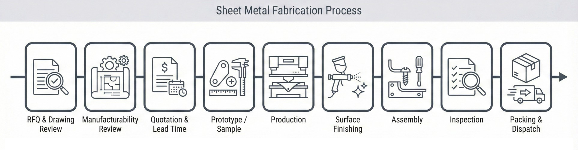
This process starts when the customer sends an RFQ with drawings. After reviewing the RFQ and drawings, we contact the customer if any clarification or design change is required from our side.
We then share the quotation with lead time and shipping details. Pricing is shared clearly based on the drawing and scope.
A prototype is provided when required before mass production. The sample part is shared with the customer for approval.
After approval, we start production. Manufacturing, finishing, assembly, and packaging are done according to customer requirements.
Parts are inspected before dispatch. After final inspection, parts are packed and shipped.
Surface finishing and coating are handled through qualified partner facilities. Finishing is applied based on customer specification and part application.
Common finishing options include anodizing for aluminum parts and zinc or nickel plating for steel parts. Chemical treatment using nitric solution is applied for brass parts when cleaning preparation is required. Wet painting is rare and supported only on specific request. Powder coating is supported but is not commonly applied to sheet metal parts.
Passivation and corrosion treatment are available on request and are not part of standard processing.
Deburring is mandatory for all parts. Sharp edges are manually removed before parts move to finishing or assembly. Cosmetic edge finishing after coating is not performed unless specified in the drawing.
Standard packaging includes polythene bag packing, inner paper boxes, and master cartons. For sea shipments, parts are palletized using wooden pallets.
Custom packaging such as printed boxes or logo branding is supported on request and is chargeable.
Fabricated parts include electrical enclosures, neutral bar, mounting brackets, and terminal covers. These components support equipment mounting, insulation, and protection.
Sheet metal brackets, guards, covers, and support structures are used in industrial machine builds. All parts are produced strictly to OEM drawings.
Applications include sheet metal cabinets, access panels, doors, and rack-mount frames. These components provide mechanical protection and controlled access.
HAVC sheet metal fabrication parts include formed panels, ducts, mounting plates, and structural supports. Design focuses on fit, rigidity, and installation compatibility.
Custom sheet metal parts such as brackets, panels, frames, and formed profiles are supplied for OEM products. These parts are typically used in repeat production programs.
We prefer STEP (3D) and PDF together. For complex parts, a 3D file is required. DXF and DWG files are also accepted. Providing both 3D and PDF helps avoid misunderstanding and quotation delays.
RFQs without drawings are difficult to handle. We usually accept RFQs only with drawings. For very simple or standard parts, RFQs without drawings may be possible. In such cases, all dimensions must be clearly defined.
Clear RFQs help us quote faster and more accurately. We recommend including:
More complete information helps avoid back-and-forth questions.
We do not accept 1–5 pieces for OEM production parts. For sampling and quality checks, quantities of 5–10 pieces are common and supported. Minimum order quantity depends on part complexity and repeat volume.
Yes. We support both domestic and international shipping. For samples or low quantities, air shipping is preferred. For bulk production, sea freight is more economical but takes longer.
Shipping cost is paid by the customer. In some cases, free samples may be offered. Customers can also arrange pickup from our location if required.
Lead time depends on part geometry, quantity, and manufacturing complexity. There is no fixed lead time for OEM parts. Final lead time is confirmed during quotation.
Design clarification during the RFQ stage is not chargeable. If the drawing changes after quotation, a revised quotation is issued based on the changes.
Yes. Prototype or sample approval is required before starting mass production.
For parts requiring special tooling or molds, the cost is borne by the customer. Tooling costs are quoted separately and discussed before production.
To request a quotation, please send your drawing along with RFQ details.
Please include the following information:
After receiving the RFQ, we review the drawings and specifications. If clarification is required, we contact the customer before quotation. Quotation, estimated lead time, and shipping details are shared based on the confirmed scope.