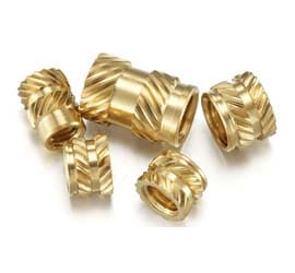
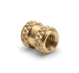
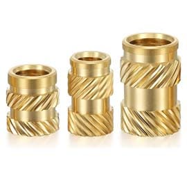
Brass knurled inserts have a patterned outside surface designed to improve retention in the host plastic material, and the knurl can help resist rotation and contribute to pull-out resistance after installation.
We manufacture custom brass knurled inserts in different sizes, thread configurations, knurl patterns, lengths, and custom designs according to customer drawings. Our brass knurled threaded inserts are used in electronics, automotive, and molded plastic components. We manufacture different knurl patterns, including straight, diamond, and helical knurling patterns, and different insert configurations such as headed, unheaded, flanged, blind, through-hole, and expansion inserts. We support both inch and metric thread configurations.
We support medium- to high-volume production requirements. Samples and a small batch are also supported for quality and testing.
We supply brass inserts to OEMs, distributors, and industrial buyers in the United States, Asia, and across European markets, including Germany, France, Spain, the Czech Republic, the Netherlands, the UK, and Italy.
Request a Quote for Custom Brass Knurling InsertsThe external knurl on a brass threaded insert provides mechanical grip within the host material. Its primary function is to resist the insert from turning when the mating screw is tightened. This resistance is referred to as torque-out resistance. Additionally, the insert's pull-out resistance is influenced by several factors, including its length, diameter, knurl design, host material, hole size, and installation method.
Different knurl patterns are suited to various installation methods. Straight knurls are typically used for heat and ultrasonic installations when high torque resistance is needed. On the other hand, helical knurls are employed in some press-in designs to offer both torque and pull-out resistance, while also aiding in the insert's entry into the hole during installation.
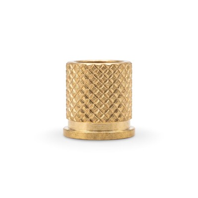
Material: Brass
Insert Type: Diamond knurl flange insert
Thread: ISO Metric (M6)
Knurling Configuration: Diamond
Overall Height: 11.00 mm
Knurling Length: 8.70 mm
Flange Thickness: 1.20 mm
Step Height: 1.30 mm
Body Outside Diameter: 10.30 mm
Flange Outside Diameter: 11.15 mm
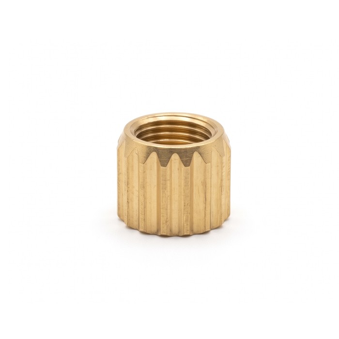
We manufacture this custom brass diamond knurl flange insert with an M6 internal thread, 10.30 mm body diameter, and 11.15 mm flange diameter. The brass knurled insert has an 8.70 mm diamond-knurled section, a 1.30 mm step, and a 1.20 mm flange that forms the integrated mounting profile.
Material: Brass IS 319 Grade 1
Knurling Configuration: Stright Knurling insert
Thread: M4
Overall Height: 6.75 mm
Knurled Section Height: 4.50 mm
Upper Dimension: 6.00 mm
Diameter: Ø6.00 mm
Diameter: Ø5.75 mm
Diameter: Ø4.75 mm
Knurling Detail: 0.4 × 16 knurls
Angular Feature: 30°
We manufacture this custom brass Knurled insert with an M4 internal thread, 6.75 mm overall height, and 6.00 mm diameter. The knurled brass insert features a 4.50 mm externally knurled section with 0.4 × 16 knurling, along with Ø5.75 mm and Ø4.75 mm diameter features and a 30° angular profile.

Material: Brass IS 319 Grade 1
Insert Type: Knurled threaded insert
Knurling Configuration: Diamond
Thread: ISO Metric M6
Overall Height: 13.90 mm
Outside Diameter: 10.30 mm
Step OD: 8 mm
Middle Step Height: 2.40 mm
Upper Knurl Height: 4.85 mm
Lower Knurl Height: 4.85 mm
Body Design: Stepped cylindrical profile with upper and lower diamond-knurled sections
We manufacture this custom brass diamond-knurled insert with an ISO Metric M6 internal thread, a 10.30 mm outside diameter, and a 13.90 mm overall height. The brass knurled threaded insert uses upper and lower 4.85 mm diamond-knurled sections around an 8 mm stepped center with a 2.40 mm middle section.
| Specification | Details |
|---|---|
| Manufacturing Method |
Dedicated automatic brass insert machines CNC machining for Large and Special Insert Requirements |
| Materials |
Brass C36000 Brass CW614N(CuZn39Pb3) Brass IS 319 Grade 1 Custom grade according requirements |
| Brass Knurled Insert Shapes |
Round knurled body Unheaded knurled inserts Headed and flanged knurled inserts Blind-threaded knurled inserts Through-threaded knurled inserts Slotted and expansion knurled inserts Custom brass inserts as per requirements |
| Typical Size Range |
Small to big inserts used in plastic molding (exact limits reviewed per drawing) |
| Thread Types |
Metric: M2, M2.5, M3, M4, M5, M6, M8, etc. Imperial: #2-56, #4-40, #6-32, #8-32, #10-24, 1/4-20, and other UNC/UNF sizes according to drawing Blind and through threads as per design and other custom specified threads |
| Knurl Type | Straight, Diamond, Helical/Diagonal, Cross, and Annular knurling. custom knurl patterns and external retention features according to requirements. |
| Dimensional Control |
OD typically around ±0.10 mm depending on size Tighter tolerances reviewed case by case according to drawing. |
| Thread Control | Go/No-Go gauge checks at regular intervals during production |
| Surface Finish |
Nitric/Cleaning as default Nickel and tin plating via partners |
| Inspection & Documentation |
Visual check for burrs Vernier / digital calipers, Go/No-Go thread gauges, Material test reports / mill heat certificates on request CMM and profile inspection via partners |
| Packaging |
Bag + label for standard orders Master Box + Wooden pallet |
| Lead Time |
Repeat orders: approximately 15-20 working days New orders: 25-30 working days Exact production time depends on the insert design and drawing. |
| Production Volume |
Prototype / sample before batch (1–10 pcs) Medium and repeat OEM production preferred Standalone very small orders (10–50 pcs only) not supported |
| Drawings Accepted | STEP (3D), PDF, DXF, and DWG files |
| Tooling Ownership | All tooling are customer-owned Tooling is never reused for other customers |
We manufacture brass knurling inserts from diffrent outside knurl patterns. Common knurl patterns include straight, diamond, and helical knurls.
Straight lines outside of the insert's body. They provide strong resistance to rotation and are commonly used on brass threaded inserts for press-in, heat, and ultrasonic installation designs.
Diamond knurls form a crossed pattern on the outside of the brass insert. They provide mechanical engagement with the surrounding material and are used on selected insert designs, including molded-in designs.
Helical knurls follow an angled path around the outside of the brass insert. In press-in designs, the helical pattern can provide resistance to rotation and pull-out while allowing the insert to rotate as it enters the hole. Some heat and ultrasonic insert designs also use opposed helical knurls for retention in thermoplastics.
| Knurl Pattern | Basic Shape | Typical Retention Characteristic | Example Installation Context |
|---|---|---|---|
| Straight | Straight lines around the insert | Strong resistance to rotation | Press-in, heat, ultrasonic |
| Diamond | Crossed pattern | Mechanical engagement with the host material | Selected molded-in and other insert designs |
| Helical | Angled or spiral lines | Can provide torque and pull-out resistance | Press-in and selected heat/ultrasonic designs |
The knurl pattern on a brass knurling insert is selected according to the installation method and host material. Heat, ultrasonic, press-in, and mold-in methods use different installation principles, so the insert geometry must match the way it will be installed.
During heat installation, a brass heat-set insert is placed into a prepared hole in a suitable thermoplastic part. Heat softens the plastic around the insert, allowing the material to flow around the external knurls and other retention features. After cooling, the plastic holds the insert in place.
Ultrasonic installation uses high-frequency vibration to generate heat at the interface between the brass knurling insert and the surrounding plastic. The softened plastic flows around the external knurls and retention features as the insert is driven into the prepared hole. After the vibration stops, the plastic cools and secures the insert.
Press-in installation places the brass press-in insert into a prepared hole without melting the plastic before insertion. The external retention features engage with the surrounding material as the insert is pressed into position. Helical knurls are used on some press-in designs to provide torque and pull-out resistance while helping the insert enter the hole.
During mold-in installation, the brass molding insert is positioned in the mold before the plastic part is formed. The insert is held on the mold tooling while the plastic flows around its external features during molding. After molding, the insert remains integrated into the finished part.
| Installation Method | How It Works | Typical Host Material | Knurl / Retention Design |
|---|---|---|---|
| Heat | Heat softens the plastic and allows it to flow around the insert | Suitable thermoplastics | External knurls, grooves, undercuts |
| Ultrasonic | Ultrasonic vibration generates heat and softens the surrounding plastic | Suitable thermoplastics | Knurls, grooves, undercuts matched to the insert design |
| Press-In | Insert is pressed into a prepared hole without pre-melting the plastic | Selected plastics, depending on insert design | Helical, straight, barbed, and other retention features |
| Mold-In | Insert is positioned in the mold and the material forms around it | Thermoplastics and thermosets, depending on design | Knurls, undercuts, grooves, external retention features |
We manufacture custom brass knurled inserts with various body and end configurations. Our Common configurations include round knurled bodies, unheaded and headed designs, blind and through-threaded versions, and slotted expansion designs. These features can be combined in the same insert according to the required application.
Round knurled inserts have a cylindrical body with an external knurled surface. The knurl provides mechanical engagement with the host material, and the internal thread provides the fastening point. We manufacture custom body diameter, insert length, thread size, and knurl dimensions according to the drawing.
Unheaded knurled inserts have no projecting head above the insert body. The top of the insert can sit flush with the surrounding material, making this design useful where a low-profile surface is required. We make them with different knurl and thread configurations according to the drawings.
Headed knurled inserts have a wider section at the top of the body. The head provides a larger bearing surface and can help resist pull-through in suitable applications. Depending on the design, the head can also provide a contact surface for the mating component.
Blind-threaded knurled inserts have an internal thread that stops before the bottom of the insert. The closed end can help prevent the host material from entering the threaded area during molding. This configuration is used when the screw does not need to pass completely through the insert.
Through-threaded knurled inserts have an open threaded passage through the insert. This configuration allows a screw to pass through the full threaded length and can suit assemblies where access beyond the insert is required.
Some brass knurled inserts include slots that compress the insert body during installation and allow it to expand when the screw is installed. The expansion feature works with the surrounding material to retain the insert after installation.
| Configuration | Main Feature | Typical Purpose |
|---|---|---|
| Round Knurled Body | Cylindrical body with external knurl | Mechanical retention in the host material |
| Unheaded | No projecting head | Low-profile and flush installations |
| Headed / Flanged | Wider head at the top | Larger bearing area and improved resistance to pull-through |
| Blind-Threaded | Internal thread stops before the bottom | Closed-end applications and protection of the threaded cavity during molding |
| Through-Threaded | Thread passes through the insert | Applications where the screw can pass through the insert |
| Slotted / Expansion | Slots allow controlled expansion | Press-in retention using expansion of the insert body |
Our knurled insert is used in various applications such as electronics, automotive plastic components, appliances, communication equipment, and electrical assemblies.
In electronic housings, electrical enclosures, switch housings, and molded electronic modules, brass knurled inserts provide threaded mounting points for securing covers, circuit-related components, and other parts to plastic housings.
Automotive plastic components use brass knurled inserts in electronic modules, interior parts, housings, and other molded assemblies.
For plastic home appliances, control assemblies, and other molded appliance components, brass knurled inserts provide threaded fastening points for attaching covers, panels, and internal components.
Communication equipment housings and molded enclosures can use brass knurled inserts for reusable threaded points that secure covers, brackets, boards, and other internal components.
The required hole size depends on the insert design and installation method. Use the hole dimension given on the insert drawing. A hole that is too large can reduce knurl engagement, while a hole that is too small can increase installation force and stress in the surrounding material.
A brass knurled insert can spin when the surrounding material does not provide enough resistance to rotation. Common causes include an oversized hole, unsuitable knurl design, insufficient material around the insert, and improper installation. The insert, hole, host material, and installation method must be matched for the required torque resistance.
Plastic can crack when the hole is too small, the wall around the insert is too thin, or the installation process creates excessive stress. Material properties and insert geometry also affect cracking.
A heat-set brass knurled insert is generally installed flush with the plastic surface. Headed and flanged inserts can extend above the surface by design.
Yes. Brass knurled inserts are used in 3D printed thermoplastic parts to provide reusable metal threads. Heat-set installation is suitable for many thermoplastic prints, while press-in designs can be used where the insert and printed material are suitable for that method. The insert design should match the printed material and installation process.
To request a brass Knurling insert quotation, send your drawing and RFQ details.
Please include:
After receiving your RFQ, drawings are reviewed and any technical clarification is discussed if required. A quotation is issued with pricing and indicative lead time before production.
Request a Quote for Custom Brass knurled Inserts