Understanding the difference between a neutral bar and a ground bus bar is not optional. It is the core of safe panel wiring. Most mistakes in residential and commercial panels come from mixing these two parts. They look similar, but they do not behave the same in a live system.
Neutral carries return current during normal operation. Ground does not carry current unless a fault occurs. This single fact shapes every rule inside the main panel and every subpanel downstream.
Installers run into trouble when they bond these bars in the wrong place. They create hidden current paths through metal enclosures, conduits, and equipment frames. These errors do not show up on day one. They show up when something fails and the current travels through a path that was never meant to carry it.
This guide breaks the role of each bar, how they are built, where they connect, and why electrical codes separate neutral and ground in specific locations. Every section stays practical, so you can see the real difference.
Defining the Distinction: Ground Versus Neutral
Neutral is the conductor that carries return current under normal operation, back to the source.
Ground is the conductor that provides a safety path for fault current to flow to earth, and under normal operation carries no continuous current.
In a service panel the neutral and ground are bonded at a single point to establish a reference to earth.
After that bonding point the neutral and ground must remain separate in sub-panels to avoid unwanted current paths.
These differences drive how panels are wired, how bars are located, and how parties inspect equipment.
The Ground Versus Neutral Function in a Live Circuit
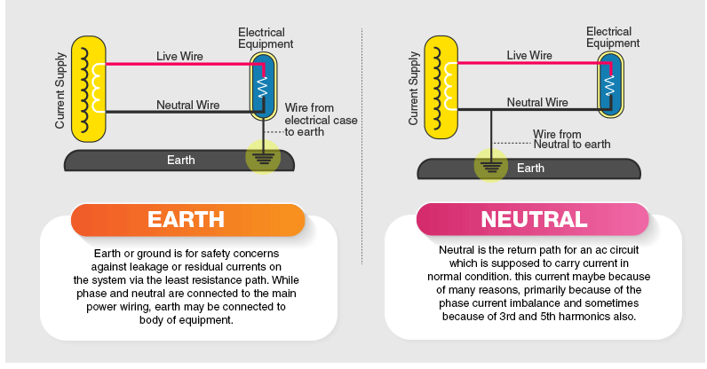
In a live circuit under normal load:
- Hot conductor supplies current (for example 120 V to a load).
- Current returns through the neutral (grounded conductor).
- Neutral is in use as part of the circuit and carries the load current.
- Ground (equipment grounding conductor) carries essentially no current.
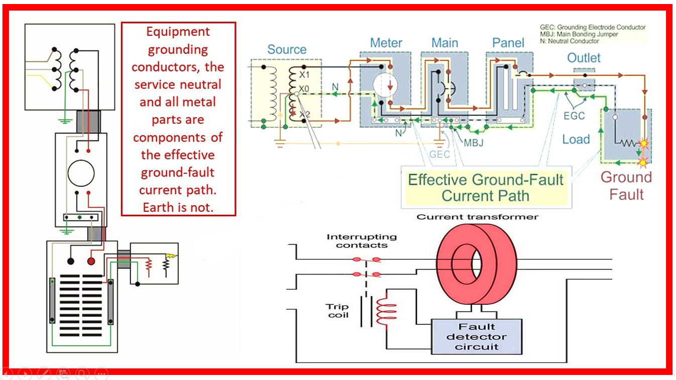
In a fault condition (live conductor contacts metal chassis):
- Fault current flows from the hot conductor to the metal chassis → into the equipment grounding conductor (EGC) → back to the service bond/earth.
- This path is low impedance so the over-current device (breaker/fuse) clears the fault.
Example with numbers:
Assume a fault causes 500 A to flow on the grounding conductor briefly. The breaker sized for 1000 A interrupt rating clears in less than 0.1 s, preventing shock hazard on the chassis. If instead the neutral and ground were bonded downstream (wrong location), normal load current of, say 10 A may split onto the metal frame and the grounding conductor, producing stray current on exposed metal. That condition is unsafe though the circuit may still work.
When Does Current Flow: Normal Operation vs. Fault Conditions
| Condition | Where Current Flows | Conductors Involved | Comments |
|---|---|---|---|
| Normal operation | Between hot and neutral | Hot & Neutral | Neutral carries return current; EGC carries negligible current |
| Fault condition | Through hot → chassis → EGC → bond → source | Hot & Equipment Grounding Conductor | EGC must carry large fault current momentarily until breaker trips |
| Improper bonding | Neutral current flows partly on ground system | Neutral & Ground mixed | Creates unintended current path and hazard |
Fault current example: If a 240 V hot conductor shorts to a metal enclosure and the fault impedance is 0.1 Ω, current = 240 V / 0.1 Ω = 2400 A. The equipment ground must be sized to carry that current until the breaker clears. Code reference: NEC Article 250 (U.S.) mandates the grounding electrode conductor and grounding/bonding system to handle fault currents.
Understanding these conductors and flows is essential before pinning down where to locate the neutral bar, where to locate the ground bar, and how to wire panels correctly.
The Physical Components: Ground Bar vs Neutral Bar
A ground bar and a neutral bar look similar at first glance. They do different jobs inside a panel. The neutral bar stays insulated from the metal enclosure when used in a subpanel. The ground bar bonds directly to the enclosure through the mounting screws. This physical difference controls how current flows and how the panel meets code.
A neutral bar carries load-return current. It must not touch metal parts in a subpanel. A ground bar carries fault current only. It must touch the enclosure to give a direct safety path. These mechanical differences decide how the system behaves under normal load and during a fault.
In many control panels the neutral termination uses brass neutral bars or DIN-mounted terminal blocks. Larger load centers use aluminum or a heavy-duty copper neutral bar with higher current ratings.
The Ground Bar vs Neutral Bar: Physical Design and Connection Points
A neutral bar sits on an insulated base. The screws that hold it pass through standoffs or brass spacers so the metal bar never touches the enclosure. This insulation keeps the neutral floating in a subpanel. The neutral bar has tapped holes sized for branch-circuit neutral wires. Each hole holds one neutral conductor to prevent loose connections and shared currents.
A ground bar mounts directly to the metal enclosure with its screws. There is no insulation. The bar bonds to the enclosure as soon as the screws tighten. The holes on a ground bar follow UL listings that allow one or more ground wires per terminal depending on size and certification. The job of this bar is to give the equipment grounding conductors a direct and low-resistance path into the metal enclosure and back to the main bonding point.
A bonding screw is the key part in the main panel. This screw ties the neutral bar to the enclosure at the service disconnect. That connection is removed in subpanels. If someone installs the bonding screw in a subpanel, the neutral current will flow on the metal enclosure and the grounding system. That mistake creates shock hazards.
Are the Ground Bar and Neutral Bar the Same in Material? (Busbar Construction)
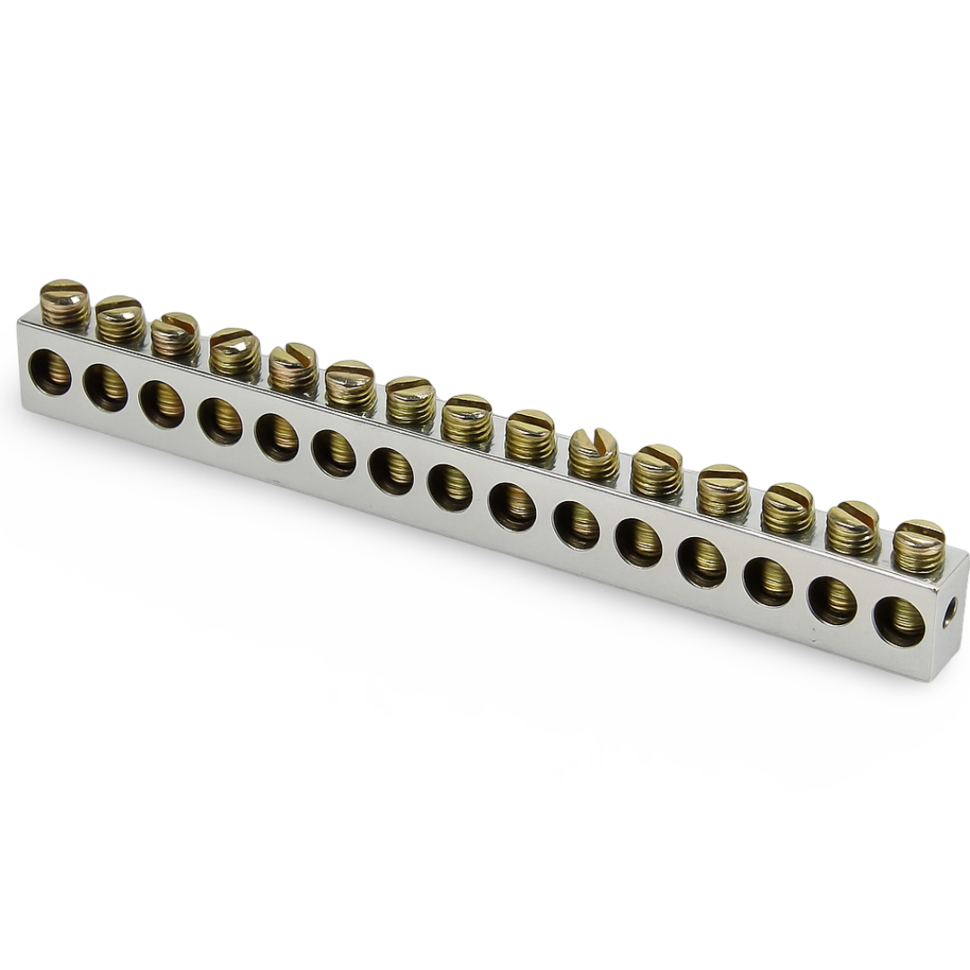
Neutral bars and ground bars do not use one universal material. The material depends on the type of electrical system and the certification requirements. Many control panels, distribution boards, and small OEM enclosures use Brass neutral links and brass earth links. Brass works well in these systems because it machines clean, holds screw threads, and resists corrosion in compact wiring blocks. These brass links handle normal current levels found in control circuits and small load centers.
Some installations use brass neutral bars in control panels, while larger systems rely on copper neutral bar or aluminum neutral bars. Aluminum–Copper Spacers are used when connecting mixed-metal conductors to prevent galvanic corrosion
A main neutral bus bar in a high-power panel is made from copper or aluminum. These materials handle higher current and higher fault levels. UL-listed and IEC-certified panel boards follow this rule because brass cannot carry the fault current required for service equipment. Copper bus bars may come bare or tin-plated. Aluminum bus bars often come tin-plated to resist oxidation. The plating does not change the function. It only prevents corrosion at the wire contact points.
Ground bars follow the same material logic. Larger panels use copper or aluminum bonding bars that mount directly to the metal enclosure. The function depends on how the bar is installed and bonded, not only on the metal used to make it.
The Critical Electrical Difference in Panel Wiring
Panel wiring depends on one rule. Neutral and ground connect together at the main service panel. They must stay separated in every subpanel. This rule controls current flow, fault clearing, and safety. If someone violates this rule, the metal enclosure becomes a return path for load current. That mistake creates shock risk. It also breaks the purpose of the grounding conductor.
A main panel has the bonding point. A subpanel must not have it. This is the difference that protects the system.
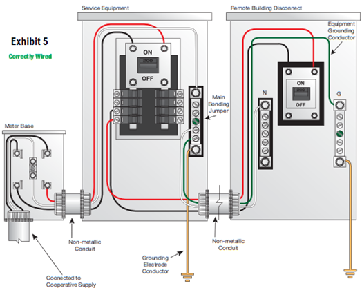
Main Service Panel: Where Bonding Is Required by Code
The main service panel is the first point of disconnect. The neutral must bond to the panel enclosure at this location. A bonding screw connects the neutral bar to the metal enclosure. This bond ties the grounded conductor to earth. It gives the fault current a low-impedance path back to the source. The breaker needs this path to trip fast during a fault.
At the main panel, neutral and ground sit at the same electrical potential. Both bars connect to the same reference point. This is the only place this connection is allowed. The system needs one bonding point. A second bonding point anywhere else creates parallel current paths.
The main service panel must always contain:
- The neutral-to-ground bond
- The grounding electrode conductor
- The equipment grounding conductor connection
- The first disconnecting means
This is the code-defined location where the connection must happen.
Subpanels: Why Neutral and Ground Must Be Isolated
A subpanel is downstream from the main panel. The neutral bar must stay insulated from the enclosure. The ground bar must bond to the enclosure. These two bars cannot touch. If someone installs the bonding screw in a subpanel, neutral current will flow on the metal frame, conduits, and grounding conductors. That condition makes the enclosure live. A person touching the cover during a fault or open-neutral event can get shocked.
A subpanel must receive four wires from the main panel. Hot, hot, neutral, and ground. The neutral wire lands on the isolated neutral bar. The ground wire lands on the bonded ground bar. This separation keeps each conductor in its correct role. Neutral carries only return current. Ground stays ready for fault current only.
This isolation rule protects every load downstream. It also prevents parallel paths, nuisance shocks, and weak fault clearing. A subpanel that mixes neutral and ground is unsafe and does not meet electrical code.
Safety, Risks, and Installation Best Practices
Panel safety depends on correct bonding and correct separation of neutral and ground. A small wiring mistake can place current on metal parts that people touch. A loose neutral, a wrong bonding screw, or a shared terminal can turn a safe panel into a risk. Good installation practice removes these hazards before the power turns on.
Safety in a panel starts with correct conductor placement. It continues with tight terminations, clean routing, and proper separation of return paths and fault paths. When these basics stay correct, the panel works safely for years.
The Danger of Improper Bonding
Improper bonding sends current through places that should never carry current. A neutral tied to the enclosure in a subpanel will place load current on metal parts. That condition makes the enclosure energised during normal operation. A person can receive a shock when touching the cover or conduit.
A missing bonding screw in the main panel creates the opposite problem. A fault will not clear fast because the breaker cannot see enough current. The enclosure stays live until someone touches it or the system fails somewhere else.
An open neutral causes another major hazard. It can place full voltage on equipment frames through connected loads. That condition damages appliances and creates fire risk. Bonding must stay correct at the service panel so the system remains stable when a fault occurs.
Improper bonding also creates parallel paths through grounding conductors. These paths reduce fault clearing speed and increase the chances of hidden heating inside conduits, connectors, and panel hardware.
Correct bonding prevents these failures. Wrong bonding guarantees them.
Installation Checklist: Common Mistakes to Avoid
Use this checklist to avoid the most common and dangerous wiring errors:
- Never bond neutral and ground in a subpanel.
- Always remove the bonding screw in a subpanel.
- Keep the neutral bar isolated from the enclosure.
- Bond the ground bar directly to the enclosure.
- Land neutral and ground wires on separate bars.
- Use one neutral per terminal hole.
- Do not mix neutral and ground conductors in the same terminal.
- Use the correct four-wire feeder for subpanels: two hots, one neutral, one ground.
- Confirm torque values on all lugs and terminals.
- Keep all conductors clean and free of insulation damage.
- Verify ground continuity from the panel to the grounding electrode system.
- Inspect the panel again after energizing to confirm no heating or abnormal current paths.
These steps prevent unsafe conditions, improve reliability, and ensure the panel meets electrical standards.